USF Electrical Engineering Design I
Spring 2020
Product Context:
The DSP Parametric Equalizer provides a way for users to unlock more control of music or audio from devices using a 3.5mm jack. It can change the frequency response of the input signal, i.e. more low-end or cutting out the highs. This device is intended to be used on top of a desk and will operate best when connected to in-ear monitors or headphones. There are not many products that can provide the amount of utility and control such as this.
User Scenarios/Use Cases
-
The product will need to be connected through a 3.5 mm audio jack to a music player, phone or any other device that can produce an audio signal. The parametric equalizer will have a volume knob and three knobs for the following filtering parameters: gain, center of frequency and Q-factor. Both the signal and filtering parameters chosen by the user, will be sent to the DSP, which after modulation in real-time will be sent to the headphones.
-
Our product will not fit into a business scenario, since it is mostly for a recreational use. Student A has a multiple genre playlist on his/her phone and would like to play it while doing homework. First, a pop song plays which his/her headphones sound okay, but the next song is a hip-hop song, which does not sound as good with the same filter parameters. With our product interfering between the audio signal and the headphones, the student could filter the audio file according to its genre and/or wanted filtering parameters to sound better.
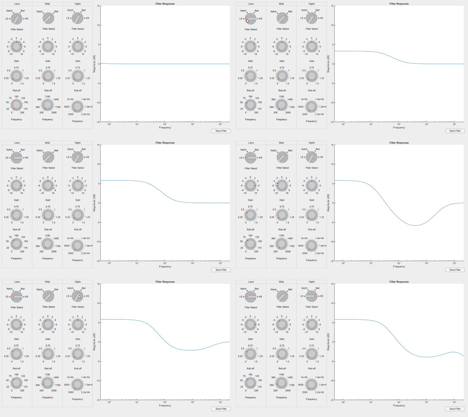
UI Filter Generation Demo
(Matlab)


Diagrams:
Sequence Diagram:

Data Flow Diagram:

System State-Transition Diagram:

CAD Drawing of the Product Chassis with measurements:

SYSTEMS INTERFACES
Internal System Interfaces
a. MCU to DSP
Description: MCU will write to DSP memory to input IIR filter coefficients
i. SPI Interface (I2C will be used during development)*
ii. Memory Written with ‘Safeload Writing’ method
● Safeload allows for parameter rewriting without rebooting the DSP
● Data is written in 28-bit words with four leading 0s to create a
b. DSP to Amplifier
i. DSP will send analog converted signal to be amplified to be sent to the output audio jack
External System Interfaces
a. Analog Input
i. Input will be compatible with any system that has an audio output that can convert to a 3.5 mm audio jack
ii. Inputs levels should be of ‘line-in’ levels not exceeding 0.9 Vrms at the input
b. Analog Output
i. Audio output will be configured for typical headphone (50Ω) impedance.
ii. ¼ inch headphone jack shall be used
System Requirements Matrix

Requirements Test Matrix

Documents

